E1DA Cosmos ADCiso Analog-to-Digital Converter Review
I was going to write a review of good earphones, Truthear HEXA, but it seems like there is a more important topic. And it’s not even about the importance, but about a total absence of Russian-language (and, actually, any) smart documentation for a unique device – the E1DA Cosmos ADCiso analog-to-digital converter. It seems to me that many people would be interested to know about this device, but due to the fact that its author markets it as a device for DIY people, this ADC hasn’t got a lot of play, or rather a very narrow group of a chosen few knows about it, and even fewer people know how to use it. And of all of them, only two or three guys decided to write about it in detail.
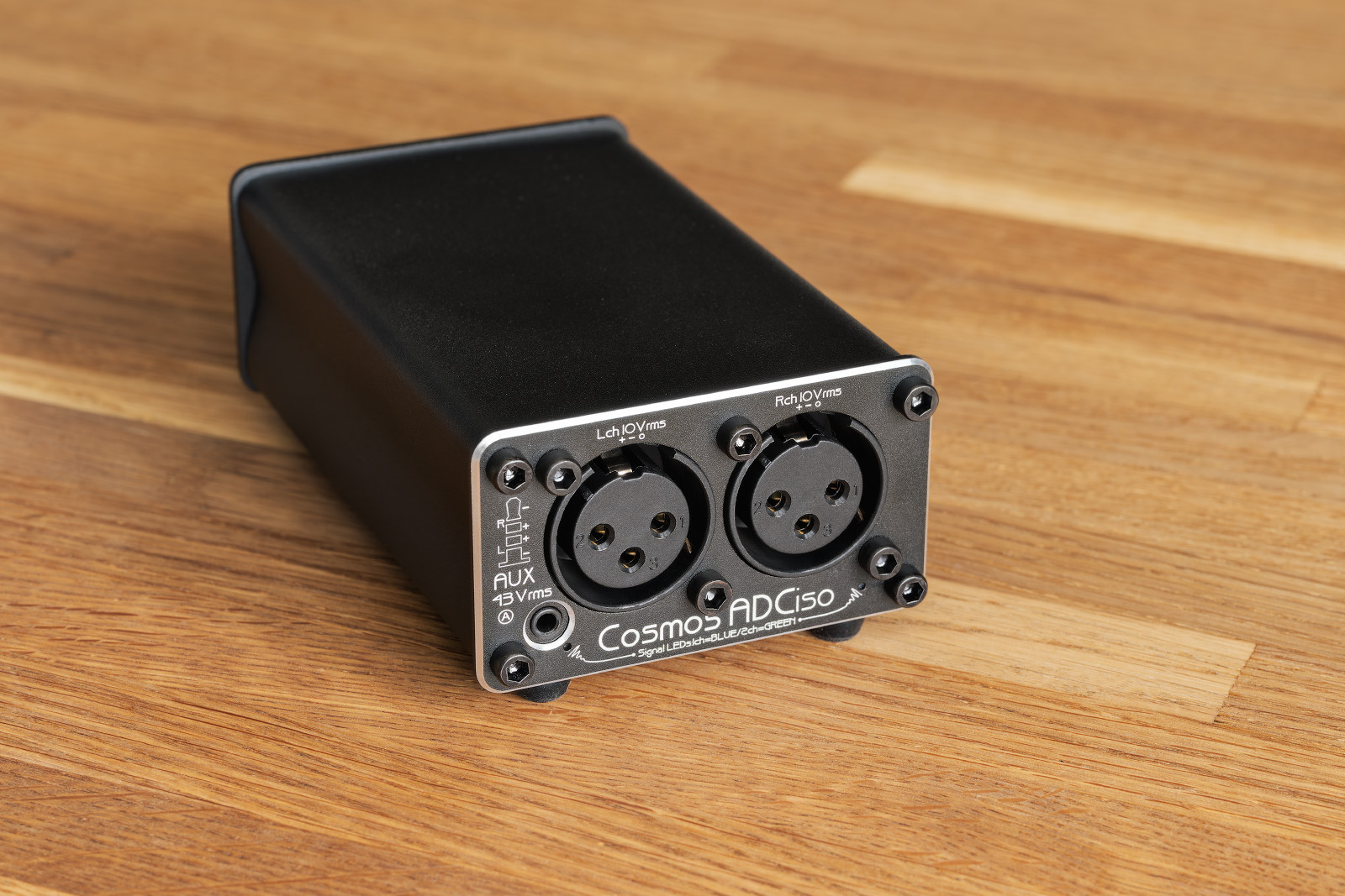
I’ll try to fix this situation somehow because the device is worth it. Consider the following text as an attempt to write coherently about the ADC itself, as well as the process of using it. It’s sort of a loose (and certainly incomplete) user manual if you like.
And before you ask, here are my words of gratitude to the users of the manufacturer’s Discord channel: E1DA (Ivan Khlyupin), Nick_l (???), and all the others who patiently answered my questions, helped, analyzed, suggested, etc. This text would never appear without you. Thank you to the moon and back!
1. Important premonitions
- This article is about the device and the measurement methodology. It’s not about Ivan Khlyupin, not about online drama, not about politics. It’s just about the device itself and how to use it. Anyone who brings even a drop of shit here will be banned immediately.
- I have no doubt that I will write some nonsense below or forget something crucial. If you notice this, please let me know in the comments. I will be happy to make this article better.
- The following text is based on my personal experience of using ADC, which arises from my interests and goals – measuring the parameters of amplifiers in a DAC for headphones. Therefore, I don’t set out to describe the capabilities of the device in all their vast completeness, but only in the narrow range of tasks that I personally solved with its help. If you want to learn more, all links are given at the end of the article.
2. What is it?
As the term suggests, this is an ADC, or an analog-to-digital converter. It is so low-noise and with such low distortion that it would be more correct to call it a high-precision instrument for measuring the values of various parameters of sound sources. Yes, it can be used as just an ADC, you can connect a microphone to it and even adapt it for digitizing vinyl records, but initially it was meant for a different purpose.
As far as I understood, Ivan Khlyupin wanted to create a measuring device that would allow not only registration of the parameters of sound-reproducing equipment, but also doing it up to the standards of analyzers worth of $20,000 such as Audio Precision APx555, only that the cost of the device is not $20,000, but just some $200, depending on its version (grade).
And, as far as I understand, Ivan succeeded: a lot was sacrificed; the device requires a number of certain skills and knowledge, as well as a lot of patience and a desire to understand his work. No documentation is included in the package. But the headline is that, when all comes to all, it does what was stated – it measures the parameters of sound sources to a fucking head’s breadth.
3. Naming
E1DA is a word made up of:
- E1 stands for ‘E-one’, or alternatively spelled ‘Ivan’;
- DA stands for ‘DAH’ (‘YES’ in Russian).
Altogether, it’s ‘IvanDAH’.
ADCiso:
- ADC stands for an ‘analog-to-digital converter’;
- Iso stands for ‘isolated’. I’ll tell you about what’s isolated in this device below.
4. Appearance, inputs and outputs
The device is a black metal box with the dimensions of approx. 10×6×4 cm and weighing about 160 g.
There are two USB Type-C ports on the back: the left one is for the cable through which the data will go, and the right one is for power supply.
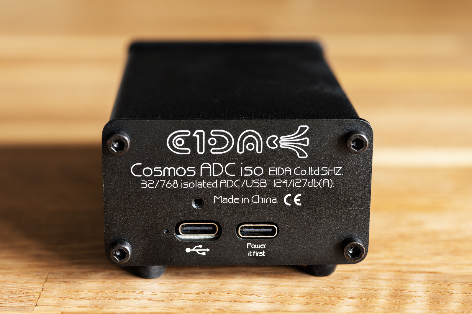
There are two ports because the power line and the data line of the ADC are completely separated. Besides, there is a hole for a diode on the back side (to the left of the data port) indicating the sampling rate of the input signal:
- 1 flash per 2 seconds: 48 kHz;
- 1 flash per second: 96 kHz;
- 2 flashes per second: 192 kHz;
- 4 flashes per second: 384 kHz.
There are three input connectors at the front.
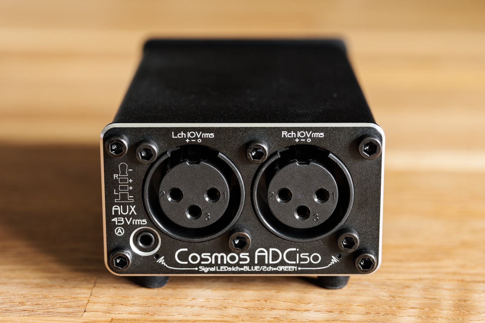
There are two 3-pin XLR connectors, as well as a 2.5 mm input jack. All inputs can be used in unbalanced and balanced modes. There are also two diodes on the left and right indicating the input signal receiving mode:
- green — stereo mode (see Sec. 6) AND the signal strength is in the range from -30 to 0 dBFS;
- blue – mono mode (see item 6);
- red — overload (0 dBFS).
There are 12 microswitches located below – 6 each for the left and right input channels – to control the range of input voltages that are in connection with the ADC’s own impedance.
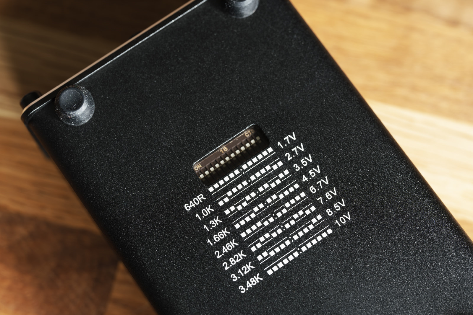
As you can see from the legend, the device processes signals with RMS voltage from 1.7 to 43 Vrms, and the impedance varies from 640 to 13,600 Ohms respectively, while the maximum voltage is 10 Vrms for XLR inputs and 43 Vrms for a 2.5 jack.
It’s possible to set up the ‘non-standard’ configuration of the switches. For example, setting ‘011111’ will give a value between 1.7 and 2.7 V.
Unbalanced switch settings are not prohibited, but due to the imbalance of input impedances, sensitivity to interference increases. Therefore, it’s not recommended to do so.
5. Software
When connected to a Windows 11 PC, the device does not require any special drivers, but for Windows 10, the driver must be installed manually. Recording modes up to 32 bit/768 kHz are supported.
As for ASIO support, there is no native driver, but FlexASIO and ASIO4ALL do their work (from what I tried). I liked the first one better.
An important feature is the principle of operation of the ADC sound slider: it controls the operating mode of the device (see the next section).
Additional features:
- The utility program E1DA Cosmos Tweak Windows app allows configuration of ‘subtle’ internal parameters of the device such as interpolation filters and so on. Personally, I didn’t use it.
- It’s possible to change the device firmware using a native app. Again, I didn’t use it.
Regarding the compatibility of ADC with well-known measurement applications, I can note correct operation in REW and Arta. As for RMAA, some unclear ‘floating’ problems appear from time to time.
6. Operation modes
The device supports three operation modes. The mode is selected by the system volume slider:
- Stereo mode (volume slider at 0 in Windows): the device works as a 2-channel ADC.
- Mono mode (volume slider at 100 in Windows): the signals from the left and right channels are summed and transmitted to the left channel. See the notes on the cable desoldering diagram in the next section.
- RIAA curve mode (volume slider somewhere between 0 and 100 in Windows): a mode for digitizing vinyl records. I haven’t used it, so I can’t say anything about it.
The main difference between the modes is SNR and dynamic range: the mono mode exceeds the stereo one by 3 dB, that is, it allows even more precise measurements.
7. Cables and desoldering diagrams
I’m interested in amplifiers and DACs for headphones, so I needed to get the output signal from the following connectors:
- TRS 3.5;
- TRS 6.3;
- TRRS 2.5;
- TRRS 4.4;
- 4-pin XLR.
There are other options, too, but they’re quite exotic. And, since it’s necessary to ensure high measurement accuracy, it was decided to order the manufacture of high-quality short cables:
- TRS 3.5 → 2 × 3-pin XLR;
- TRS 6.3 → 2 × 3-pin XLR;
- TRRS 2.5 → 2 × 3-pin XLR;
- TRRS 4.4 → 2 × 3-pin XLR;
- 4-pin XLR → 2 × 3-pin XLR.
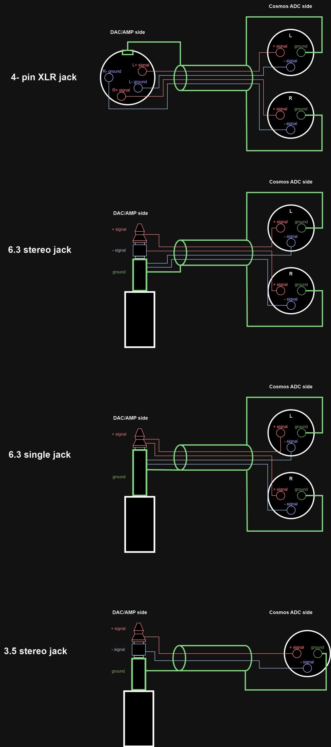
Bear in mind that for mono mode, a cable with L+ and R+, L- and R- connected contacts is required. Here are the desoldering diagrams of the cables most commonly used for measuring ‘headphone sources’:
This is my personal set:
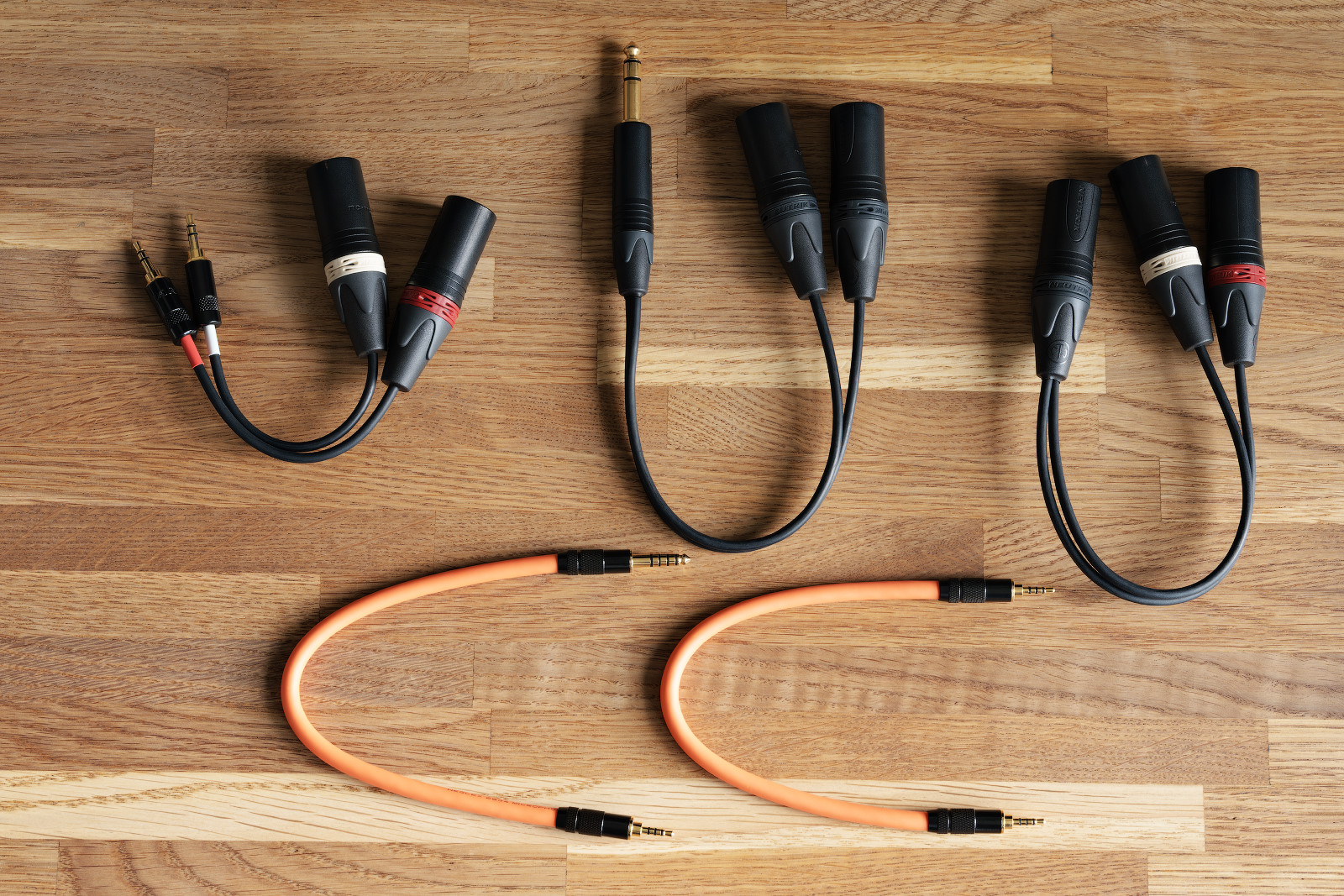
Well, and a few adapters, too.
8. Additional cables and hardware from the manufacturer
8.1 Original USB Type-C Cable
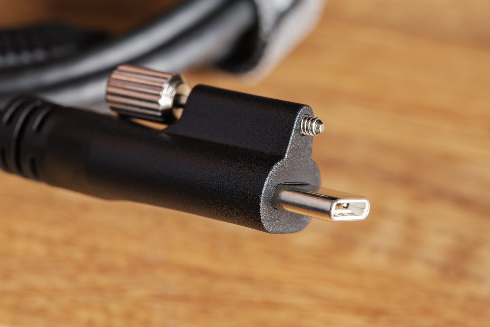
The manufacturer draws attention to the fact that the Type-C ports of the device can quickly wear out if the cable is frequently removed from/inserted into the connector. Therefore, the manufacturer offers a solution, or an original USB 3.0 Type-A → Type-C cable 1.2 meter long with a locking screw.
Attention: it is forbidden to use a screwdriver to tighten the screw. Tighten it only manually, taking hold of the knurled head.
8.2 Load board
Testing audio equipment without load is not a representative story and generally a quite useless one. The manufacturer offers a separate load board, which allows:
- simulation of load from 10 to 300 Ohms or giving no load at all. The impedance can be set up by ten switches on the front side of the board;
- connection of real headphones as load. In this case, the first 10 switches must be down. At that, it’s not recommended to combine load from the board and from the headphones.
- take readings under load.
Please pay attention to the position of the last two switches: for an unbalanced connection, they must be up (‘ON’), while for a balanced one, they must be down. This is important: if a balanced source is connected and the switches are ‘ON’, a short circuit will occur (setting ‘ON’ bridges R- and L-).
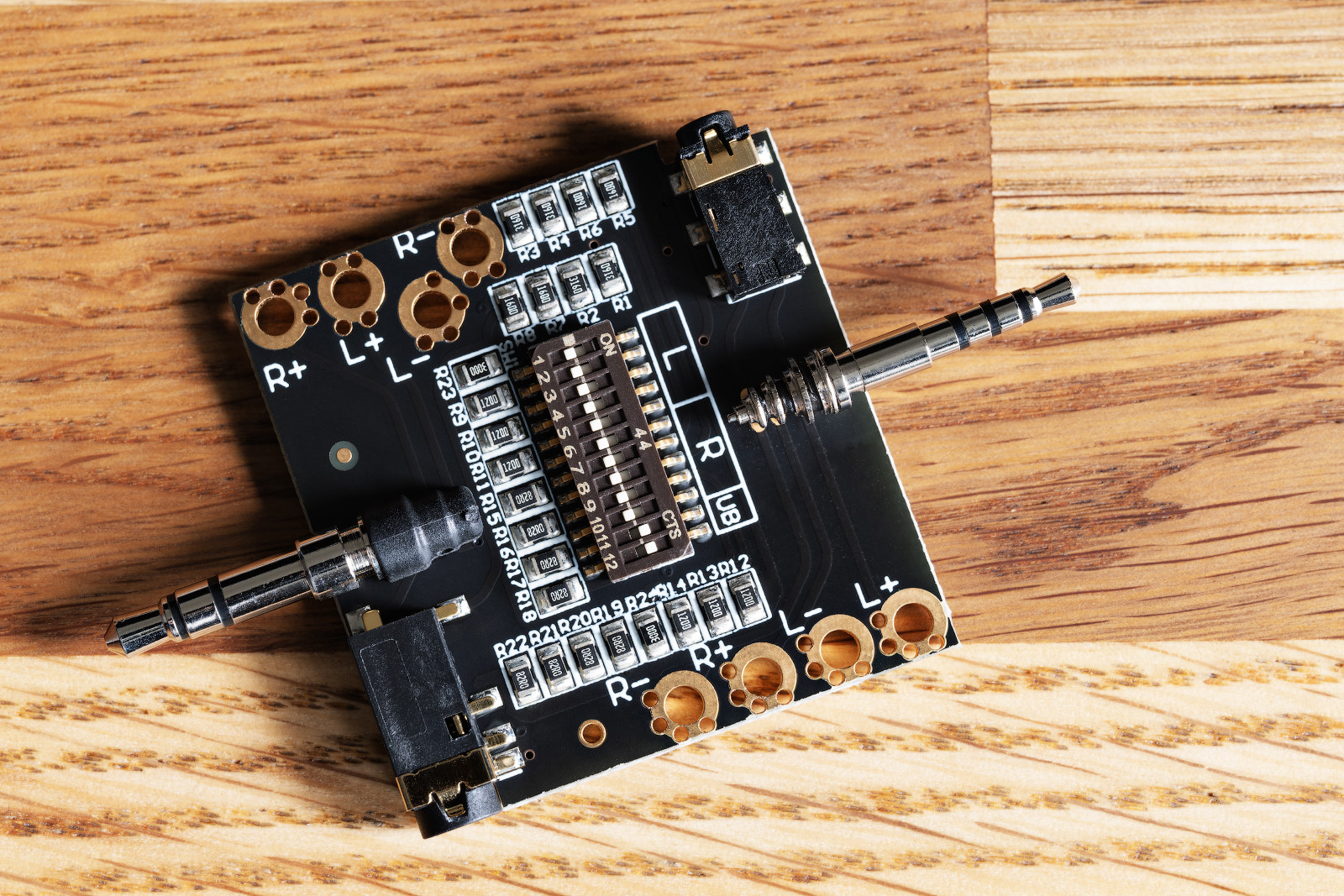
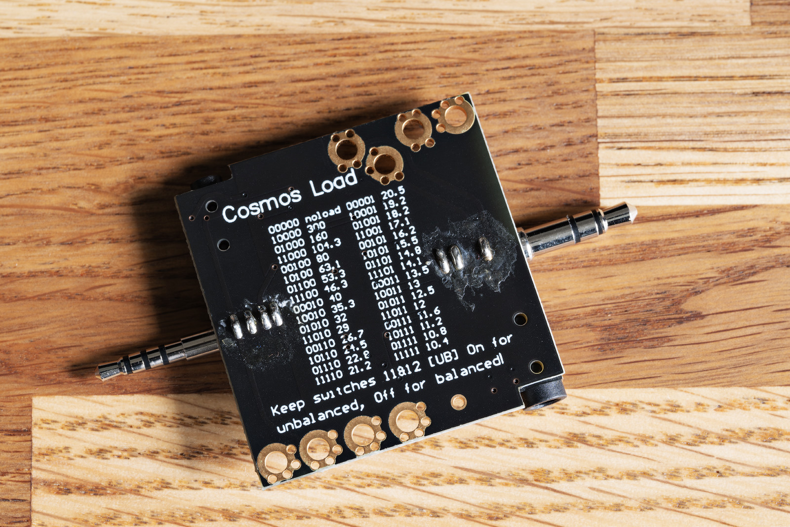
The board has two connectors, 3.5 TRS and 2.5 TRRS, and allows connection of any headphones to it. There are also contact pads for connecting probes on the sides of the board.
8.3 Cables for connection to the load board
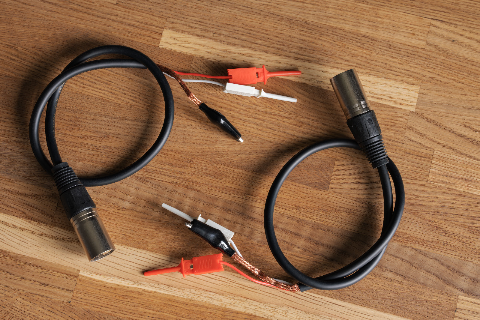
These are specialized cables that are necessary for use with the load board. From one side, there are 3–pin XLR connectors; from the other side, there are two clamp probes for + and – per each, as well as a crocodile clip that needs to be connected to the ‘ground’.
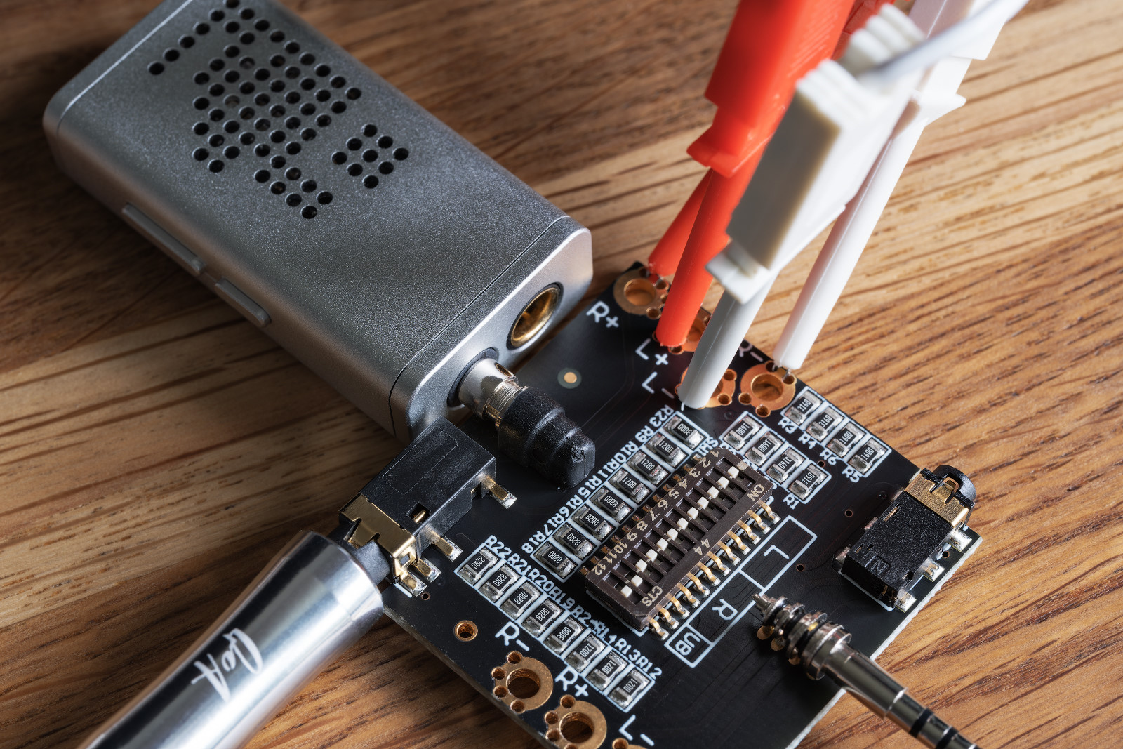
The pattern of connection to the load board, for instance, for an unbalanced connection, is as follows:
For a balanced connection, you need to use another connector and contact pads on the other side of the board. The headphones are also connected to a cater-cornered output.
9. Quick specifications overview
- Hardware platform: ES9822Pro chip, OPA1612, RT6863S amplifiers, CT7601CR audio bridge.
- Required power supply: 5 V.
- Frequency measurement range: 8 Hz – 320 kHz.
- SNR: 125-129 dB (depending on the grade of the device) in mono mode.
- THD: from -135 to -145 dB (depending on the grade of the device) at a frequency of 1 kHz at a signal level of 0.5 dBFS.
- Channel separation level: from -140 to -153 dB at a frequency of 1 kHz with channels closed and unused.
Complete specifications can be found on the manufacturer’s website.
10. Actual experience
Here are some notes and tips based on my actual experience:
1. When connecting the ADC to a PC, you must first plug in the device and only then connect it to the PC.
2. In order to minimize noise during measurements, it’s recommended to supply power to the device from a booster battery. I tried several models by Samsung and Xiaomi, as well as Hyper – everything worked fine, and the measurements were not affected in any way.
3. In order not to worry the power port too much, I use these magnetic cables. As for the measurements, there is no difference from ‘just Type-C cables’.
4. To reduce noise during the measurements, I tried using Topping HS01/02 isolators. My practice has shown as follows:
- within the limits of available measurements, the isolators have no effect on the ADC;
- within the limits of available measurements, the isolators do have an effect on the source if it is powered by USB. In my particular configuration, there is a peak from -145 dB and 50 dB below. When using the isolators, it’s not visible up to the level of -170 dB and can no longer be measured below.
5. The switches for switching the ADC signal level can be used at any time without turning off the device.
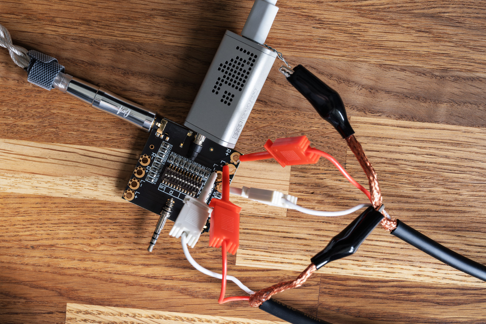
6. When using cables with probes, it’s recommended to connect ground as follows:
- Attach one crocodile clip to the ground of the second cable.
- Attach the crocodile clip of the second cable to the USB connector that powers the source. If you can’t do it directly, you can use a metal wire:
11. The procedure for making measurements
I will describe it the way I personally did it.
Point of departure: the measured DAC and ADC are not connected to the PC; the necessary software is not installed on the PC.
2. Put the ADC upside down on the table.
3. Put a toothpick on the table.
4. Look at the DAC specifications and set the appropriate voltage value on the ADC by poking at the switches with a toothpick. For example, if the DAC is able to output 2.2 Vrms at maximum, then set the nearest value on the ADC, which is bigger than 2.2 – this is 2.7.
5. First, connect the power supply to the ADC.
6. Then connect the ADC to the PC.
7. Go into the sound settings and check where the slider is. Set it to 0 or 100, depending on your goal.
8. Connect the measured DAC via a USB isolator and set the hardware volume to 100% on it.
9. Connect the ADC and DAC one way or another. If you’re using a load board, check the positions of the last two switches.
10. Launch REW and open the Preferences window (Ctrl + Shift + E).
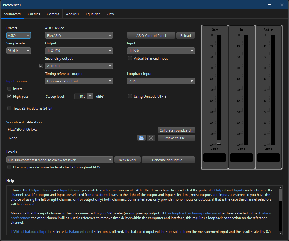
11. On the Soundcard tab, select FlexASIO in the ‘ASIO Device’ field. Click the ‘ASIO Control Panel’ button. In the FlexASIO Control Panel window that appears, select the value ‘Windows WDM-KS’ in the ‘Driver type’ field. Select the ADC and the measured device in the ‘Input device’ and ‘Output device’ fields respectively. Click the ‘Close panel and update config file’ button.
12. Type in all the other values. You’ll get something like this:
13. Click the ‘RTA’ button (Ctrl + Shift + T) and the ‘Generator’ button (Ctrl +Shift +R). The windows of the realtime signal analyzer and generator will appear on the screen. In what follows, it’s recommended to keep these two windows simultaneously open on the screen.
14. In the RTA window, check that the ‘Show distortion’ button is pulled. If it is clicked, then the analyzer may screw up in the absence of a signal, and REW will simply crash.
15. In the RTA window, click on the gear icon (upper right corner) and set up the following settings:
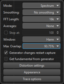
16. In the RTA window, click the ‘Start/stop the RTA’ button. If you see a twitching polyline like one shown below, the ADC is working correctly:
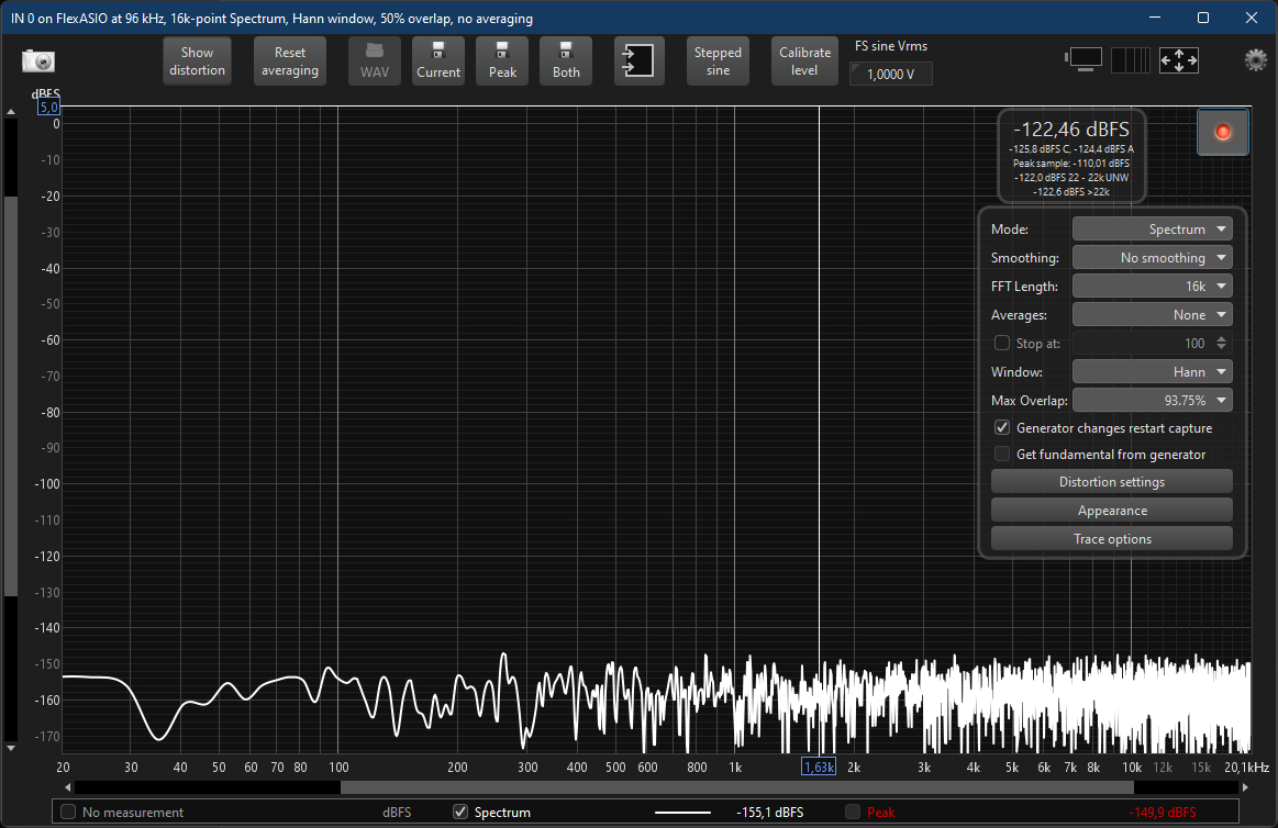
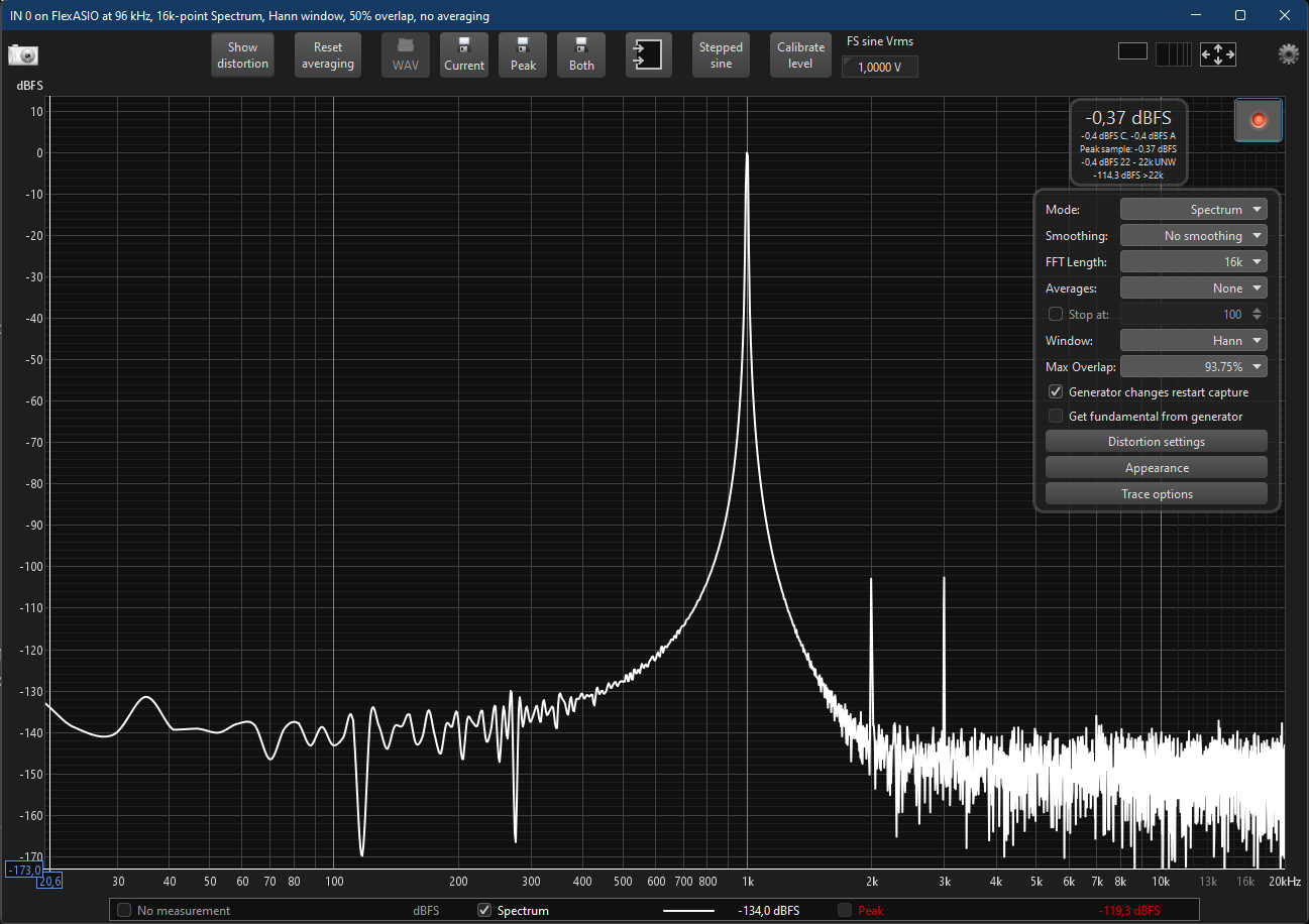
17. In the generator window, select Tones → Sine, Frequency Hz = 1000, Add dither = 32 bits, 0 dBFS. In the ‘Output’ fields, select the channels, click the button with the green triangle, and look at the RTA window.
18. If you see something like this in the RTA window, then everything works:
19. Change RTA settings to the following:
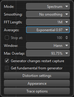
20. Make ‘final’ measurements:
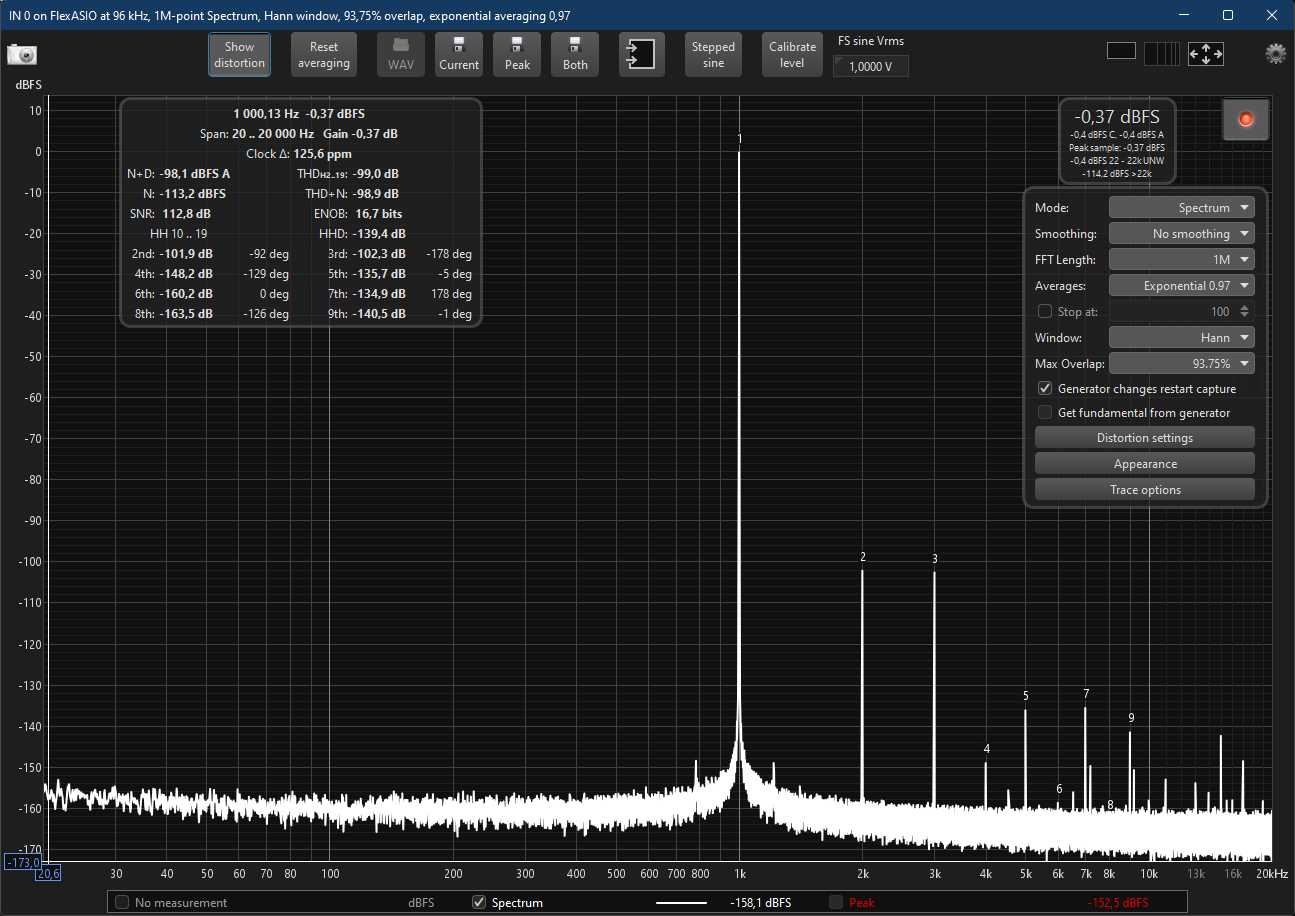
All that is left to do to send various signals by means of the generator to the ADC via the DAC and to analyze the results. But that’s another story.
And, of course, we are interested in measurements in the range from -1 to 0 dBFS.
12. What’s to be done if…
1. You connected the ADC, launched RTA, but the level curve is at a very low level and doesn’t move:

There’s a 99 percent chance that you connected the ADC to the PC and only then powered up the ADC. Disconnect it and connect it correctly.
2. You connected the ADC, launched RTA, but you see some crap like this:
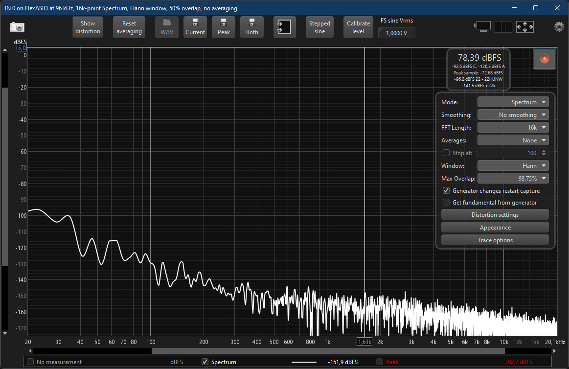
The volume slider is somewhere between 0 and 100. Place it back.
3. You connected the ADC, launched RTA, started the generator, but you see some distortion, and the signal level is more than 0 dBFS:
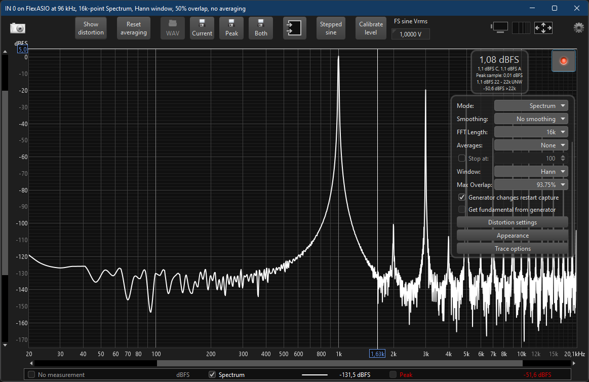
You made incorrect voltage settings on the ADC. They need to be boosted up.
4. You connected the ADC, launched RTA, started the generator, there is no distortion, but the signal level is below -1 dBFS:
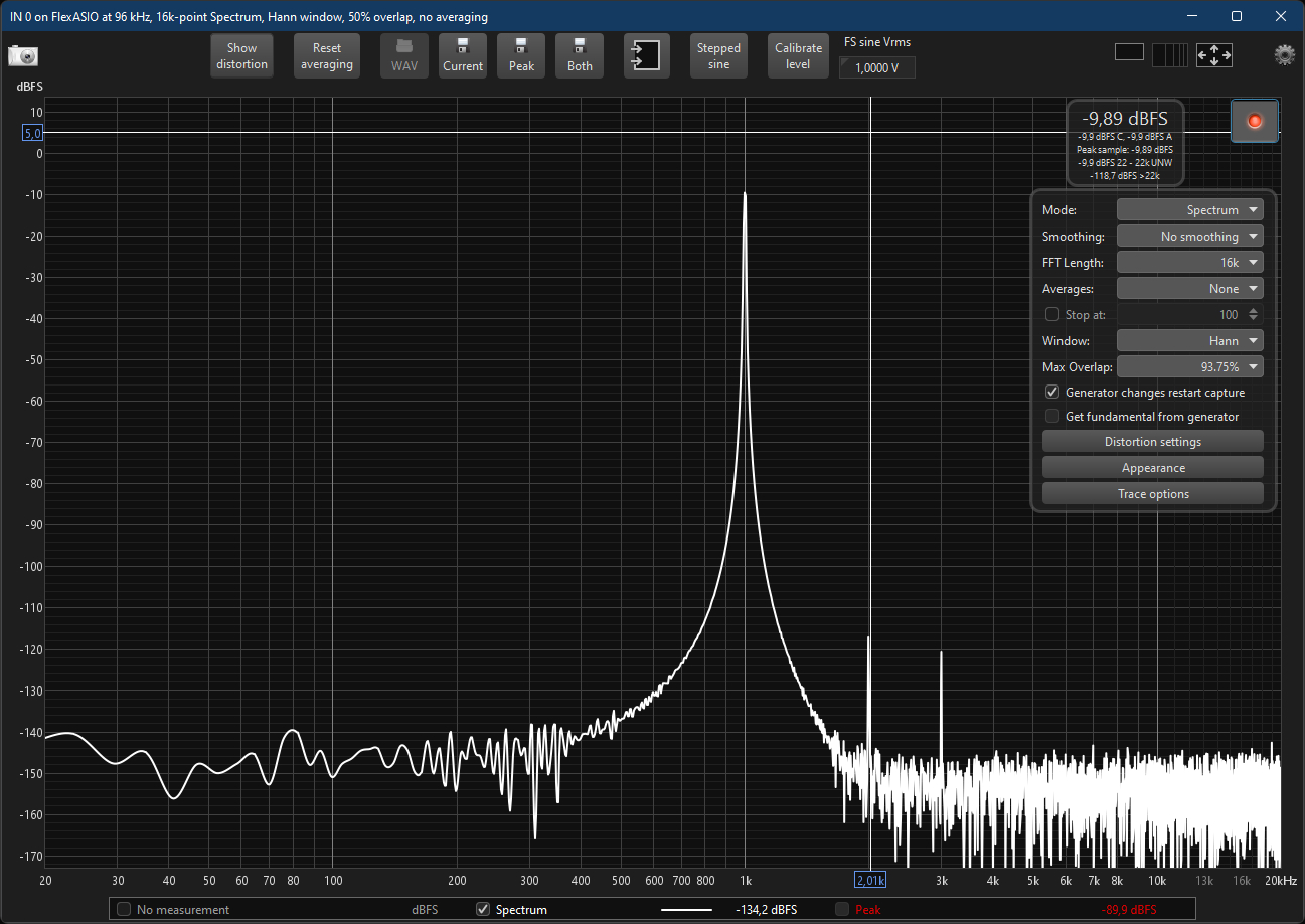
If the hardware volume level of the source is set to maximum and the signal level in REW is set to 0 dBFS, then you need to reduce the voltage settings on the ADC by one position and then figure out such a dBFS value in REW so that the signal level falls into the desired area [-1.0] dBFS.
It is also likely that you are sending a signal to one channel, but the ADC is ‘listening’ to another channel. Then you just need to adjust the REW settings.
But if the ADC is set to the minimum voltage and the volume levels are turned to the maximum everywhere, then you will need an additional device from the Cosmos line: Scaler or APU. I’ll surely tell about them next time.
13. Summary
Cosmos ADC can be scolded, and for a lot of things, especially for the monstrous ergonomics: an inconvenient display system with diodes located on two different sides of the device, an inconvenient arrangement of switches for voltage selection, inconvenient switches themselves, diodes too strongly recessed into the housing, the light of which is visible only at a certain angle, a complete lack of user documentation, etc.
However, it seems to me that it’s pointless to scold the device.
Firstly, Cosmos ADC is sort of a … ‘shovel’ for enthusiasts. It’s unique, it’s not marketed by the manufacturer as the most convenient one, you need to learn how to use it. But the holes dug with this shovel are the best. In fact, this is a device that was originally made ‘to one’s own cheek’, but then it was released to the public.
Secondly and most importantly, Cosmos ADC has no competitors in its price niche in terms of significant characteristics. There are no competitors even for 10 times more money. Something functionally similar is made by QuantAsylum. The model is called QA403 Audio Analyzer (QA401 is off the market), which costs $600 and is significantly inferior to Cosmos ADC in a number of characteristics — here is even a respective comparative table, although it has isolators, generators, as well as its own software. In that table, by the way, you can also look at prices of the devices that are comparable to Cosmos ADC in terms of characteristics.
Therefore, I would characterize Cosmos ADC as a user-unfriendly, poorly documented engineering marvel.
My to-buy-or-not-to-buy recommendations, which I usually end my texts with, are obviously out of place here. You’ve either already rushed to order this device or haven’t even read down this far.
14. Useful links
- Discord with news and discussions. Questions are allowed.
- An awesome article about a device by Archimago.
- Measurement of amplifiers with Cosmos ADC at OpenAudioLab.
- The inners of Cosmos ADC at audiosciencereview.
- Measurements made by Amir at audiosciencereview.
- E1DA Audio Store at aliexpress.
